Definition and Basic Functionality
A flange represents a protruded rim, collar, or rib on pipes, valves, or equipment housings designed to enable mechanical joining with other components. These circular or rectangular fittings serve as connection points within pressurized systems, facilitating assembly, disassembly, and maintenance operations. The fundamental purpose involves creating leak-proof joints between piping sections or between pipes and other equipment while withstanding mechanical stresses and fluid pressures.
 Primary Components and Construction
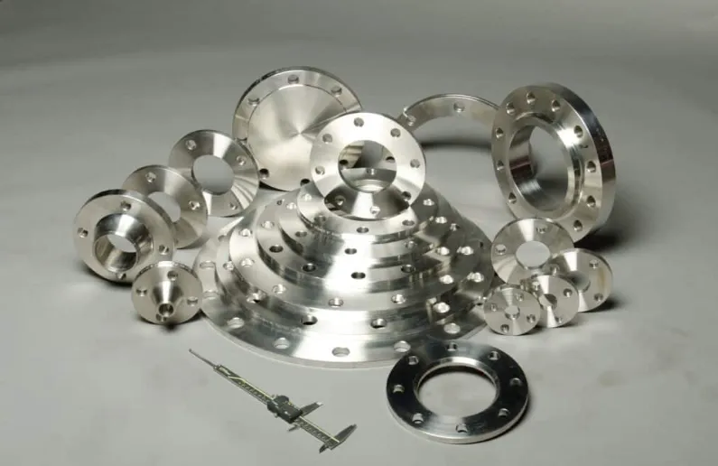
Standard flanges consist of several key elements: the flange face, which establishes the sealing surface; the bore, matching the inner diameter of the connected pipe; and bolt holes arranged in precise circular patterns. Manufacturing processes vary by material and application, including forging for high-strength steel flanges, casting for complex geometries in iron alloys, and machining from plate stock for custom dimensions. Common materials span carbon steel (ASTM A105), stainless steel (ASTM A182 grades F304/F316), and specialty alloys for corrosive environments.
Classification by Connection Method
Flange types differentiate by their attachment mechanisms and sealing principles:
- Weld Neck Flanges incorporate a tapered hub for butt welding to pipes, preferred for high-pressure systems
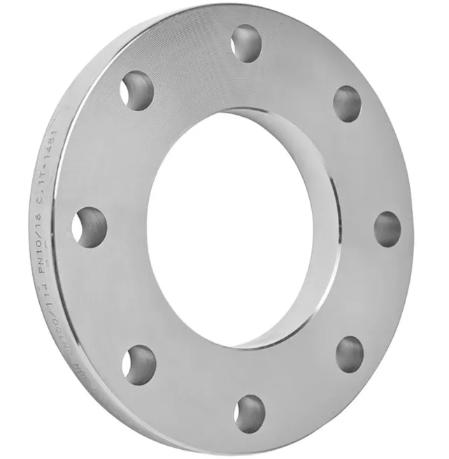
- Slip-On Flanges feature slightly larger bores for fillet welding to pipe exteriors
- Socket Weld Flanges employ interior recesses for small-diameter, high-pressure piping
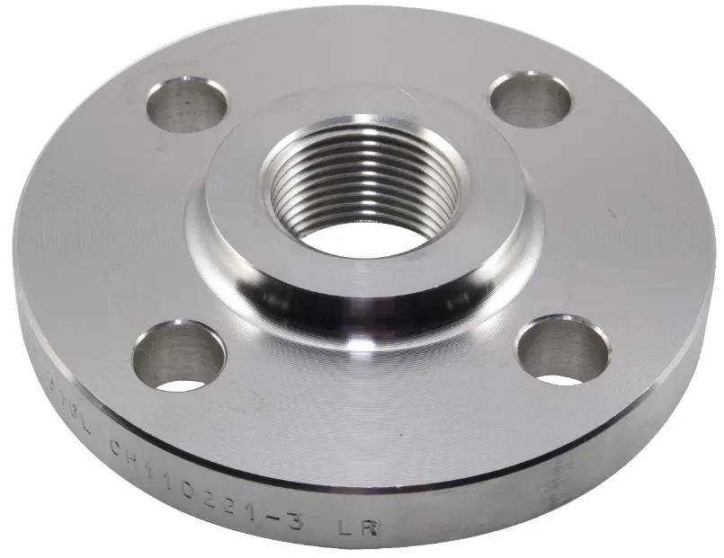
- Threaded Flanges utilize internal threads for screw connections without welding
- Lap Joint Flanges combine with stub ends for systems requiring frequent disassembly
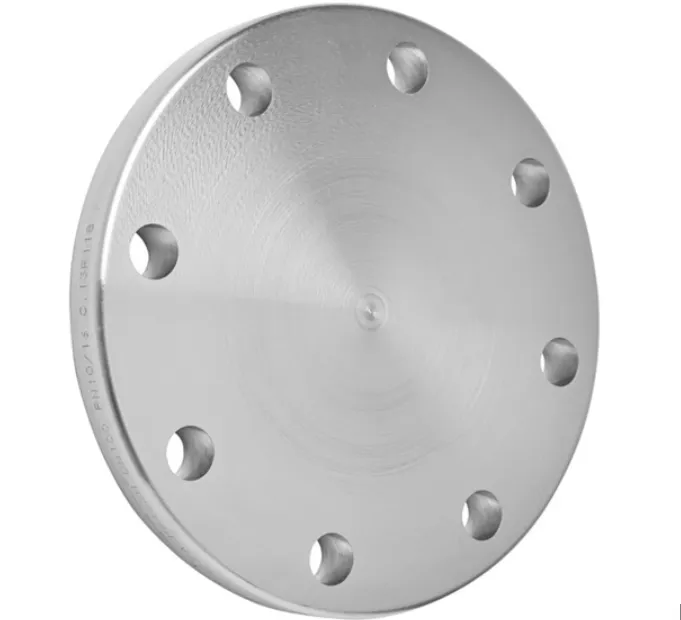
- Blind Flanges seal pipe ends or vessel openings without flow passages
Pressure Ratings and Standards Compliance
Flanges adhere to standardized pressure-temperature ratings established by organizations including ASME, ANSI, and API. The ASME B16.5 specification defines seven pressure classes (150, 300, 400, 600, 900, 1500, and 2500) corresponding to increasing pressure capacities at defined temperatures. Dimensional standards ensure interchangeability, with nominal pipe sizes (NPS) ranging from 1/2″ to over 60″ in diameter. European EN 1092 standards maintain similar classifications through PN ratings (PN6 to PN100), indicating nominal pressure in bars.
Sealing Mechanisms and Surface Finishes
Effective flange joints require precise surface finishes and gasket compatibility. Common face types include:
- Raised Face (RF): Standard 1/16″ or 1/4″ elevation for soft gaskets
- Flat Face (FF): Full contact surface for brittle materials like cast iron
- Ring-Type Joint (RTJ): Grooved faces for metal gaskets in high-pressure service
- Tongue-and-Groove: Interlocking profiles for critical sealing applications
Surface roughness specifications (125-250 μin for RF, 63-125 μin for RTJ) ensure proper gasket compression without leakage.

Installation and Bolt Load Considerations
Proper flange assembly follows engineered bolt tightening sequences to achieve uniform gasket compression. Torque specifications account for bolt material grade (typically ASTM A193 B7 or A320 L7), gasket type (spiral wound, PTFE, or graphite), and service conditions. Industry practices recommend tension-controlled bolt tightening methods, with hydraulic torque wrenches or bolt tensioners ensuring accurate preload. The ASME PCC-1 guidelines provide comprehensive procedures for joint assembly and bolt stress verification.
Industrial Applications and Sector-Specific Designs
Flange utilization spans multiple industries with specialized requirements:
- Oil and Gas: API 6A wellhead flanges withstand extreme pressures up to 20,000 psi
- Chemical Processing: Lined flanges incorporate PTFE or other corrosion-resistant materials
- Power Generation: Heat-resistant chromium-molybdenum steel flanges for steam service
- Water Treatment: Ductile iron flanges with epoxy coatings for municipal systems
- Shipbuilding: Compact flanges with reduced space requirements for marine piping
Inspection and Testing Protocols
Quality assurance measures include dimensional verification per ASME B16.5 tolerances, material certification testing (impact tests for low-temperature service), and non-destructive examination (liquid penetrant or ultrasonic testing). Pressure testing of assembled flanges follows ASME B31.3 requirements, typically involving hydrostatic tests at 1.5 times design pressure. Fugitive emission standards (ISO 15848) govern leak testing for volatile fluid services.
Maintenance and Failure Prevention
Common flange-related failures include gasket blowout, bolt fatigue, and crevice corrosion. Preventive maintenance involves periodic bolt retorquing, gasket replacement during system shutdowns, and corrosion protection through coatings or cathodic protection. Advanced monitoring techniques employ ultrasonic bolt tension measurement and thermal imaging to detect developing leaks in operational systems.
Emerging Technologies and Future Developments
Industry trends include the adoption of:
- Composite material flanges for weight reduction in offshore applications
- Smart flanges with embedded sensors for real-time pressure and temperature monitoring
- 3D-printed flanges for rapid prototyping and customized geometries
- Improved sealing technologies using graphene-enhanced gasket materials
These innovations address evolving challenges in energy efficiency, emission control, and maintenance optimization across industrial sectors.


