
Machine Frame and Structure
The CNC milling machine features a rigid cast iron or welded steel frame designed to minimize vibration during high-speed operations. The base incorporates precision-ground ways that support the moving table and saddle assembly. A vertical column houses the spindle head, which travels along linear guideways with preloaded ball bearings for smooth, accurate movement. The overall structure maintains geometric stability under cutting forces up to several thousand newtons.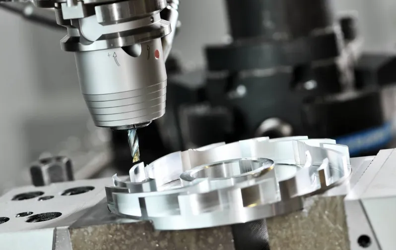 Axis Movement System
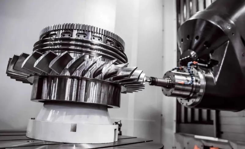
Standard 3-axis configurations employ:
- X-axis: Table movement (typically 500-2000mm travel)
- Y-axis: Saddle movement (300-800mm travel)
- Z-axis: Spindle head movement (400-600mm travel)
Each axis utilizes high-precision ground ball screws (C3-C5 grade) driven by AC servo motors with 20-bit absolute encoders, achieving positioning accuracy within ±0.005mm. Advanced models incorporate additional rotary axes (A/B/C) for complex 5-axis machining.
Spindle Assembly
The milling spindle consists of:
- High-frequency motor (7.5-40kW power range)
- HSK or BT taper tool interface
- Liquid-cooled bearing system
- Automatic tool changer interface
- Speed range from 50 to 24,000 RPM
- Torque monitoring with overload protection
Spindle runout maintains less than 0.002mm TIR at maximum speed.
Control System Architecture
The CNC system comprises:
- Industrial PC with multi-core processor
- Real-time operating system
- 15″ touchscreen HMI
- 1Gb Ethernet communication
- USB 3.0 data ports
- Fieldbus connectivity (EtherCAT/PROFINET)
The controller processes up to 1000 blocks of look-ahead data for smooth toolpath execution.
Tool Changing Mechanism
Automatic tool changers feature:
- 20-60 tool magazine capacity
- 2-5 second tool-to-tool change time
- Tool length measurement system
- Tool life management software
- Broken tool detection
- Tool balancing capability up to 25,000 RPM
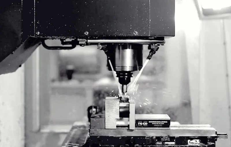
Workholding System
Standard configurations include:
- T-slot table (400x800mm to 800x2000mm)
- Hydraulic or pneumatic clamping
- Vacuum workholding (for sheet materials)
- Modular fixture systems
- 4th/5th axis rotary tables
- Pallet changing systems
Cutting Parameters
Typical operating ranges:
- Feed rates: 1-20m/min
- Rapid traverse: 30-60m/min
- Depth of cut: 0.1-10mm (depending on material)
- Stepover: 30-70% of tool diameter
- Chip load: 0.05-0.3mm/tooth
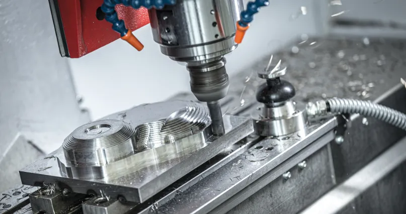
Coolant System
Integrated coolant delivery offers:
- Flood coolant (20-100L/min flow)
- Through-spindle coolant (70 bar pressure)
- Mist coolant option
- Filtration to 10 microns
- Temperature control (±2°C)
- Automatic concentration monitoring
Safety Features
Comprehensive protection includes:
- Machine enclosure with interlocks
- Emergency stop circuits (Category 3)
- Axis limit switches (hard and soft)
- Tool collision monitoring
- Spindle overload protection
- Chip and coolant containment
Programming Interface
The control system supports:
- ISO standard G-code
- Conversational programming
- CAD/CAM post-processing
- DNC operation
- Parametric programming
- 3D toolpath simulation
Precision Specifications
Manufacturer-quoted accuracy:
- Positioning: ±0.005mm
- Repeatability: ±0.002mm
- Surface finish: Ra 0.4μm achievable
- Circular interpolation: ±0.01mm
- Angular accuracy: ±15 arc seconds

Material Compatibility
Processable materials include:
- Aluminum alloys (2000/6000/7000 series)
- Steel (mild to hardened up to 60HRC)
- Stainless steel (300/400 series)
- Titanium (Grade 2/5)
- Composites (CFRP, GFRP)
- Plastics (ABS, PEEK, PTFE)
Maintenance Requirements
Scheduled service includes:
- Way lubrication (every 200 hours)
- Ball screw inspection (every 500 hours)
- Spindle regreasing (every 2000 hours)
- Coolant replacement (every 6 months)
- Filter cleaning (monthly)
- Electrical checks (annually)
Energy Consumption
Typical power requirements:
- Main spindle: 15-40kW
- Axis drives: 5-15kW
- Coolant system: 2-5kW
- Control system: 1-2kW
- Auxiliaries: 3-8kW
Energy recovery systems available on premium models.
Optional Features
Available upgrades include:
- Probing systems (tool/workpiece)
- Laser tool measurement
- Thermal compensation
- Vibration monitoring
- Automated pallet systems
- High-speed machining packages
Industrial Applications
Common manufacturing uses:
- Mold and die production
- Aerospace components
- Automotive parts
- Medical devices
- Energy sector equipment
- Defense industry applications
Operator Interface
Control panel features:
- 19″ multi-touch display
- USB data import/export
- Network connectivity
- Virtual operator keyboard
- Multiple language support
- Alarm history logging
Quality Assurance
Integrated measurement systems:
- In-process probing
- Tool breakage detection
- Adaptive control
- SPC data collection
- Process documentation
Physical Dimensions
Typical machine footprint:
- Compact models: 2.5×2.0m
- Production models: 4.0×3.5m
- Large gantry mills: 8.0×5.0m
Weight ranges from 3,000kg to 30,000kg depending on size and configuration.


