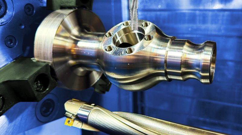
CNC (Computer Numerical Control) machines represent the backbone of modern manufacturing, transforming digital designs into physical parts through automated precision machining. These systems combine advanced mechanical engineering with sophisticated computer control to achieve accuracies within microns across various materials.
Core Operating Principle
The fundamental operation involves three synchronized components:
- Digital instructions (G-code program)
- Mechanical drive systems
- Cutting tool/workpiece interaction
 Control System Architecture
Modern CNC systems utilize:
- Industrial PC with real-time operating system
- Motion control card (handling 8+ axes simultaneously)
- Servo amplifiers with 20-bit+ resolution encoders
- Fieldbus network (EtherCAT, PROFINET) connecting peripherals
Program Execution Sequence
- CAD Model Import
- Accepts native CAD files (STEP, IGES) or 2D drawings
- CAM software converts geometry to toolpaths
- G-code Generation
- Post-processor creates machine-specific instructions
- Typical program contains:
- Motion commands (G00-G03)
- Speed/feed parameters (S/F values)
- Tool changes (M06)
- Coolant controls (M07-M09)
- Program Verification
- Virtual machining simulation
- Collision detection algorithms
- Material removal visualization
Mechanical Operation
The physical machining process involves:
Axis Movement System
- Linear guides with preloaded ball bearings
- Ball screws (C3-C5 accuracy grade)
- Direct-drive or gear-coupled servo motors
- Position feedback via rotary/linear encoders
Spindle Operation
- High-frequency motor (AC/DC) or belt-driven
- Speed range: 50-30,000 RPM (varies by machine)
- Torque characteristics:
- Constant torque below base speed
- Constant power above base speed
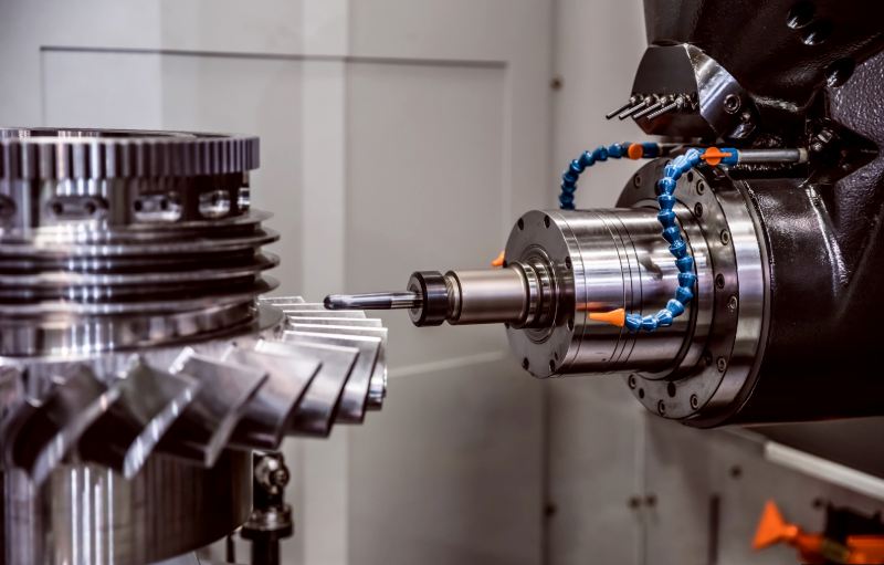
Tooling Interface
- HSK, CAT, or BT taper toolholders
- Automatic tool changers (ATC):
- Carousel type (12-40 tools)
- Chain magazine (60-300+ tools)
- Tool measurement systems:
- Laser pre-setter
- Touch probe in-machine

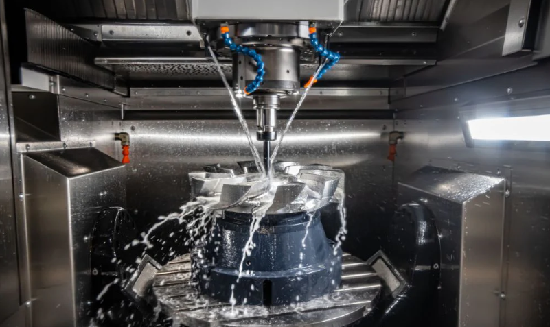
Cutting Process Dynamics
During material removal:
- Cutting forces monitored (10-1,000N typical)
- Vibration dampening systems active
- Adaptive control adjusts feeds/speeds
- Chip evacuation managed via:
- Flood coolant (5-20 bar pressure)
- Through-spindle coolant
- Air blast systems
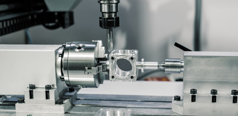
Workholding Methods
Common fixturing approaches:
- Mechanical vises (hydraulic/pneumatic)
- Vacuum plates (for sheet materials)
- Modular fixture systems
- Tombstone setups for 4-axis work
- Custom jigs for complex parts
Process Monitoring
Real-time quality assurance includes:
- Load monitoring (spindle/b-axis)
- Tool wear detection (acoustic emission)
- Thermal compensation:
- Spindle growth compensation
- Ball screw temperature control
- Vibration analysis (FFT monitoring)
Safety Systems
Critical protection mechanisms:
- Light curtains at access points
- Emergency stop circuits (dual-channel)
- Axis limit switches (hard/soft limits)
- Pressure monitoring (hydraulic systems)
Maintenance Operations
Scheduled upkeep involves:
- Way lube system checks
- Ball screw backlash measurement
- Spindle runout verification
- Coolant concentration monitoring
- Filter replacement cycles
Modern Advancements
Emerging technologies enhancing CNC operation:
- AI-based tool wear prediction
- Digital twin synchronization
- Cloud-based machine monitoring
- Augmented reality maintenance guides
- Energy recovery systems
This integrated system of precision mechanics, advanced control electronics, and sophisticated software enables CNC machines to manufacture components with micron-level repeatability across industries from aerospace to medical devices. The continuous evolution of CNC technology pushes the boundaries of what’s possible in subtractive manufacturing.


