
Test probes establish temporary electrical connections for measurement and testing applications. These components maintain contact resistance below 20mΩ while withstanding over 500,000 actuation cycles in automated test environments.
Key Performance Characteristics
- Current Capacity: 0.1-50A continuous
- Contact Resistance: <20mΩ initial (<50mΩ after life)
- Insulation: >10GΩ at 1000VDC
- Durability: 500,000+ operation cycles

Primary Probe Types
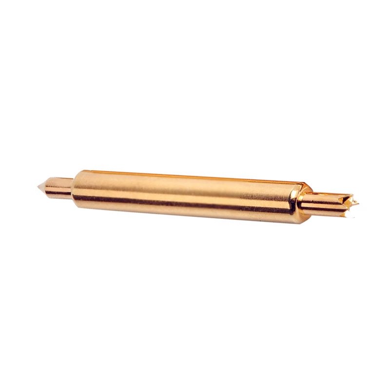
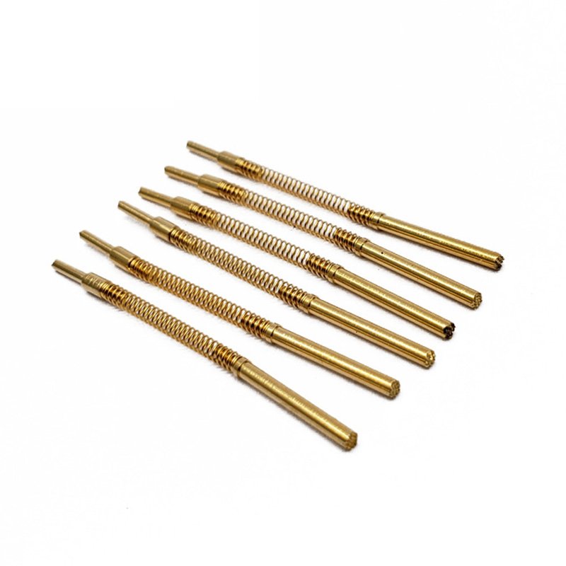
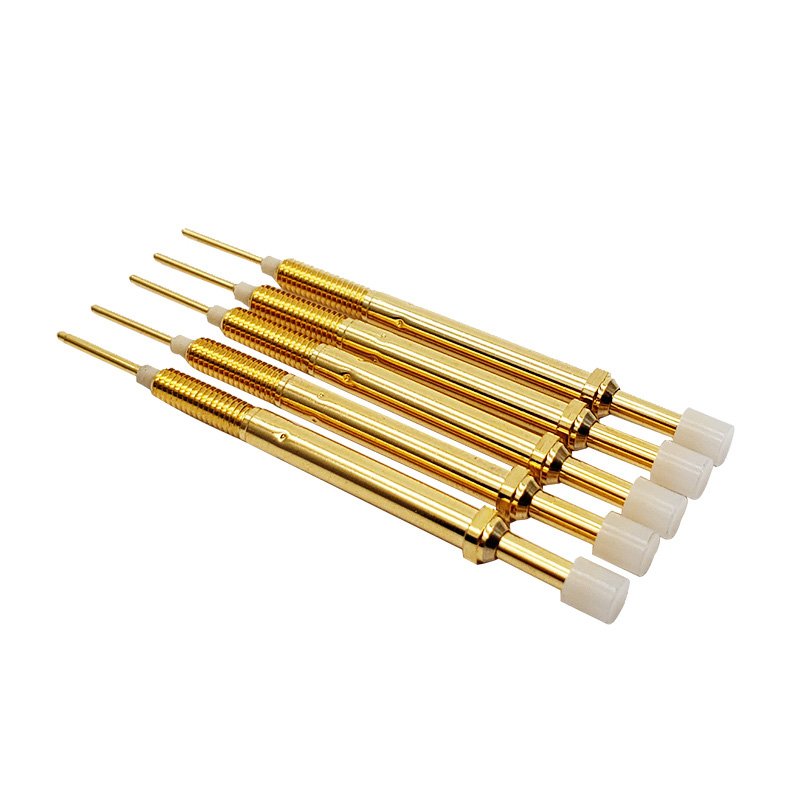
1. Spring-Loaded Designs
- Travel Range: 0.25-15mm
- Contact Force: 10-1000g adjustable
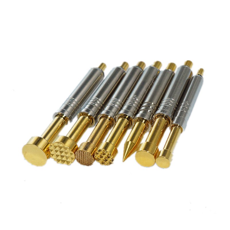
- Tip Options: Pointed, flat, crowned geometries
2. High-Frequency Probes
- Frequency Range: DC-65GHz
- VSWR: <1.5:1
- Connectors: 2.92mm/1.85mm interfaces
3. Micro-Positioning Probes
- Position Accuracy: ±5μm
- Minimum Pitch: 0.1mm
- Applications: Wafer-level testing
Technical Specifications
| Category | Current Rating | Resistance | Operating Life |
|---|---|---|---|
| Standard | 3A | <15mΩ | 500K cycles |
| Power | 50A | <5mΩ | 100K cycles |
| High-Speed | 1A | <25mΩ | 1M cycles |
Material Selection
- Contact Elements
- Beryllium copper (high elasticity)
- Phosphor bronze (general purpose)
- Tungsten carbide (abrasion resistant)
- Plating Options
- Gold over nickel (standard)
- Rhodium (high wear)
- Palladium nickel (cost alternative)
Performance Validation
- Contact Resistance
- 4-wire Kelvin measurement
- <5% variation across cycles
- MIL-STD-202 Method 307
- Durability Testing
- 500K cycle minimum
- <10% force degradation
- IPC-TM-650 2.6.7
- Environmental
- 85°C/85% RH exposure
- Thermal shock (-55°C to 125°C)
- Mixed flowing gas testing
Industry Applications
1. Semiconductor Test
- Probe card assemblies
- Wafer-level verification
- Known-good-die testing
2. PCB Validation
- Flying probe testers
- Bed-of-nails fixtures
- Boundary scan access
3. Automotive Electronics
- ECU module testing
- Sensor validation
- High-current power checks
Selection Criteria
- Electrical Requirements
- Signal frequency/content
- Current/voltage levels
- Noise sensitivity
- Mechanical Constraints
- Target pad geometry
- Available actuation force
- Pitch/density requirements
- Environmental Factors
- Operating temperature
- Contamination risks
- Vibration conditions
Maintenance Protocol
Daily:
- Visual inspection of tips
- Contact resistance spot checks
- Cleaning with approved solvents
Monthly:
- Full resistance characterization
- Spring force measurement
- Insulation testing
Annually:
- Tip replacement
- Plating thickness verification
- Complete performance recertification
Installation Best Practices
- Alignment
- <0.5° angular misalignment
- Perpendicular approach
- Optical alignment verification
- Force Calibration
- 10% above minimum requirement
- Uniform distribution
- Continuous monitoring
- Signal Integrity
- Proper grounding
- Shielded cabling
- Impedance matching


